Auto tuning a VFD is a process by which a drive measures the impedance of a motor for the purpose adjusting the motor control algorithm. The measured value may be matched to known impedance for a given motor size and used in determining voltage and current relationships at different speeds. Ultimately, this allows for more effective driving of a motor load as well as better speed regulation specifically when running without feedback ( open loop).
When not to auto-tune?
Auto-tunes are generally to be performed when the motor is cold. Auto-tuning with a hot motor may result in a variance in impedance which will subsequently cause the execution of a motor control algorithm which does not accurately match the true motor impedance.
When multiple motors are connected, an auto-tune will result in the reading of multiple motor impedances connected in parallel. Some auto-tune functions match impedance readings to known typical motor impedance values ( for instance a typical NEMA B motor). As such, the reading of multiple motor impedances in parallel can not be matched to a known motor impedance value or may match a different type of motor. This results in an unsuccessful auto-tune which may be signified by a higher than usual noise levels.
Discussion on filters when associated with drives can include line reactors, matrix filters and sinus filters among others. The filters can be on the line side of the drive for harmonic mitigation or transient protection purposes. On the load side, reactors may be used for reflected wave mitigation( caused by long motor lead lengths for example) or sinus filtering which is to filter out higher frequency components of the output of the drive to the motor.
A reactor is essentially an inductor which acts to ‘smoothen’ out the voltage on the line/load . These are typically applied in variants of 3% or 5% of the line impedance, thus reducing the voltage by 3% or 5%. Going from a reactors, other forms of harmonic mitigation may involve combination of reactors and capacitors.
The following manufacturers of power quality and filtering equipment have useful resources on the various techniques of filtering and their application in improving power quality with drives:
Following up on a previous post about the few important formulae when applying variable frequency drives specifically to ac induction motors, this post will get into the topic of constant torque variable frequency drive applications.
Voltage,Current, Torque and Speed on a Constant Torque VFD Application
What is a constant torque application? Constant torque applications may have close to a uniform torque requirement across the motor speed range. The bigger consideration from the perspective of drive selection is that these applications will require relatively high torque at low speeds compared to a pump or fan.
The actual requirement arises from the load attached to the motor. For example a connveyor may need to exert significant torque at low speeds if there are objects already on it. Another example is a progressive cavity pump which relies on positive displacement to move fluid.
Why is it important to distinguish the requirements of constant torque applications ( versus variable torque)?
1. Higher torque at lower speed requires better speed regulation capabilities within the drive. Without speed feedback from the motor, drives rely on electrical feedback in the form of current and voltage as well as phase angle vector analysis between the two to regulate the speed loop. For example, if speed drops, the drive will have to increase voltage through its IGBT gating control on the output to effect a speed increase. This determination is made continously and rapidly and in both directions ( to increase or decrease output voltage) to maintain a speed setpoint.
2. Higher torque at lower speed requires for the drive to handle higher current draw at low speed.
If torque is the same throughout – what happens to voltage and current throughout the speed range?
This is where reverting to the motor torque formula is useful.
Observations based on this formula are:
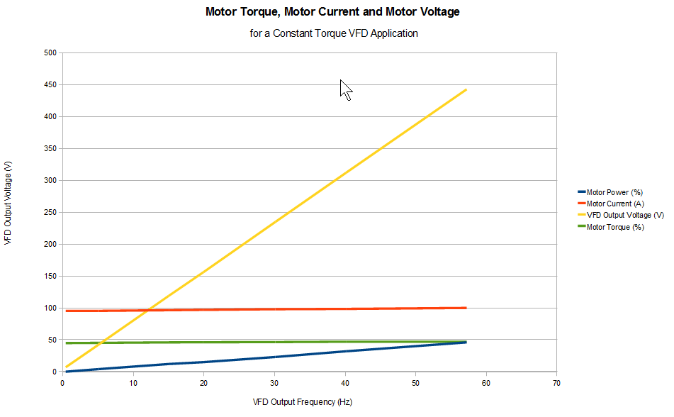
1. If torque stays the same ( constant torque) and the VFD output frequency (and motor speed) is increasing between 0-60Hz, horsepower or motor power consumption has to increase.
2. Motor power is going to be made up of two components of interest to us here ( assuming power factor and efficiency are constant) and they are voltage and current. Torque is proportional to current which infers that current will not change ( much). That leaves a variance in voltage, which also happens to be the component that the drive can alter with its voltage source inverter nature.
Some variance does occur in motor current. One possible reason is that motor impedance characteristics are affected by frequency- this is a topic of its own.
The graph at the top of this post shows the motor torque, motor voltage and motor current across the speed range. The load torque required in this example case is about 50%.
VSD’s or VFD’s , also referred to as frequency converters or adjustable speed drives, are devices that convert fixed frequency supply voltage ( typically 50Hz or 60Hz) to a variable frequency voltage. The frequency of voltage supplied to a motor determines the speed at which that motor rotates.
By Cblambert (Own work) [CC BY-SA 3.0 (http://creativecommons.org/licenses/by-sa/3.0)], via Wikimedia Commons
What are the benefits of a drive (VFD) over a motor starter?
Drives protect motors from the in rush of current when starting.
In applications where full speed operation is not required, drive saves energy by facilitating operation at lower speeds.
Drives allow for speed regulation to maintain the set point of a process ( could be a pump motor speed for pressure and flow or fan speed for temperature)
In applications where a high torque is required at a low speed, drives are able regulate both speed and torque at its output to allow for continuous operation a low speed. An example could be a hoist where the load is suspended ( at zero speed)in the air without the engagement of brakes.
Drives are able to provide current and torque limiting functionality so as to prevent motor and other equipment damage.